You are here: Experiment Guide > Nanoindentation > Procedure for Nanoindenting > Automated Indentation

Automated Indentation

Before attempting automated indentation investigations, users should first be familiar with the basic nanoindentation procedures described in the Procedure for Nanoindenting.

 
  1. Using an indentation probe, Automated Indentation.
  1. Enter the Ramp view.
 
  1. Using the Columns and Rows parameters in the Auto panel, set the number of columns and rows for the array. The Columns and Rows parameters are the number of indents to perform in the X and Y direction, respectively:

 
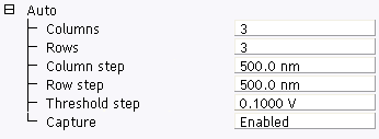
  1. Set the distance between the indents in the array using the Column step and Row step parameters in the Auto panel.

The Column step and Row step parameters are the X and Y offsets used for the array; they define the distance between two neighboring indentations along the X or Y direction, respectively.

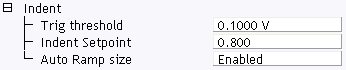
  1. Using the Trigger threshold parameter, located in the Indent panel, and the Threshold step parameter, located in the Auto panel, set the forces used for the array.For automated indentation, the force can be incremented in the X direction, using these two parameters.

The Trigger threshold is incremented by the value of the Threshold step to vary the indentation force:

  • Set the Trigger threshold to the initial value required for the deflection of the cantilever. This will be used as the Trigger threshold for the first indent in any row.
  • Set the Threshold step to the required increment for the Trigger threshold.
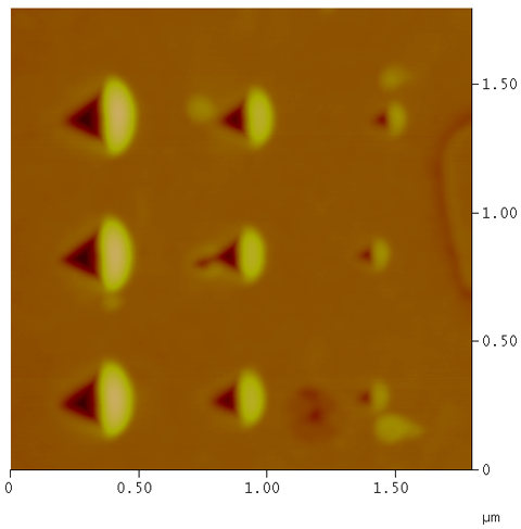
  • For example, if the Trigger threshold is 0.2 V and the Threshold step is 0.1 V, then any row of indentations in the array will be made using a cantilever deflection of 0.2, 0.3, 0.4, 0.5, ... volts.
  • The force is always incremented from right-to-left.
  • To execute an array of indentations at the same force, set the Trigger threshold to the desired force and set the Threshold step to 0.0 V.
  1. Set all other Indent Controls as desired; typical values are shown in Automated Indentation.

  1. Execute the array by clicking the Auto Ramp icon on the NanoScope toolbar.
 

The array will be executed and the force plot for each indentation will appear on the display monitor. A message box will display the X and Y offsets as the array is performed.

NOTE: To capture the force plots it is necessary to set the Capture parameter (located in the Auto panel) to Enabled before executing the Auto Ramp command. If Capture is set to Off, the indentations will be performed but the force plots will be not be captured.
 
  1. Return to the Scan view and image the indentations. The array should appear centered within the current scan.

Figure 1: Height image of automated indentation


www.bruker.com Bruker Corporation
www.brukerafmprobes.com 112 Robin Hill Rd.
nanoscaleworld.bruker-axs.com/nanoscaleworld/ Santa Barbara, CA 93117
   
  Customer Support: (800) 873-9750
  Copyright 2010, 2011. All Rights Reserved.